

Flexible and rigid-flex boards
A flex board is not a thin rigid board. It is a different construction with a different set of failure modes: the copper that carries the signal also has to survive being bent, and every extra lamination cycle is another chance for the layers to delaminate.
- Layers1 – 32
- TypeFlexible, rigid-flex
- Min line/space0.06 / 0.06 mm
- Max board650 × 1,100 mm
Flex, rigid-flex, and where the price sits
A flex board is not a thin rigid board. It is a different construction with a different set of failure modes.
A single-sided flex is one dielectric film with copper on it and a coverlay on top. It bends because there is nothing in it to crack: no glass cloth, no rigid core, and a copper layer thin enough to take the strain. A rigid-flex is that film laminated into a rigid board, so the flex portion sits buried inside the rigid stack and the two are joined by an adhesive layer — bonding, which is on our special-process list.
The price follows the number of lamination cycles, not the area. Each cycle is a press, an alignment and a chance of delamination; a rigid-flex needs at least two, and a design with two separate flex tails can need three or four. That is why a rigid-flex quote can be several times a rigid board of the same size — you are paying for the passes, and for the yield loss on each one.
What a flex design asks of the drawing is different too: the copper has to run through the bend in the right direction, the coverlay opening has to clear the bend radius, and the stiffener — if there is one — has to stop before the bend starts. All three are decided before anything is quoted.
Flexible and rigid-flex limits
Processing limits are the same as the rest of the plant; what changes is the stackup and the number of lamination cycles.
| Board type | Flexible, rigid-flexible |
| Layer count | 1 – 32 layers |
| Minimum line width / spacing | 0.06 mm / 0.06 mm |
| Copper weight | 0.5 oz – 12 oz |
| Maximum board dimensions | 650 mm × 1,100 mm (25.6 in × 43.3 in) |
| Minimum drill hole diameter | 0.1 mm |
| Minimum laser-drilled hole | 0.075 mm |
| Minimum slot width | 3.0 mm (0.12 in / 120 mil) |
| Bonding | On the special-process list — this is the adhesive layer that joins a flex core to a rigid core |
| Impedance control | Available, and usually requested on the rigid portion |
| Blind and buried vias | On the special-process list |
| Half holes | On the special-process list |
| Surface finish | HASL, ENIG, immersion tin, immersion silver, OSP, ENEPIG, electrolytic hard gold, gold fingers, ENIG + OSP |
| Quality standard | IPC-A-600F / MIL-STD-105D |
| Order quantity | 1 – 500,000 |
| Lead time | Prototype 3–4 days; mass production 8–16 days |
We do not quote a single thickness for a flex board, because the total is a product of the construction: the film, the adhesive, the coverlay and the copper weight all add to it, and so does whether the flex is single-sided, double-sided or multilayer. Send the drawing and the bend radius, and the stackup comes back as a number with a tolerance on it.
When the rigid part carries components
Most rigid-flex boards are populated, and then the assembly limits apply on top of the fabrication ones.
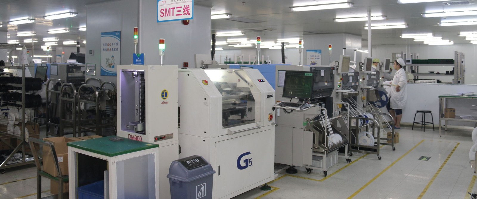
A rigid-flex goes through the same SMT lines as any other board: 24 SMT lines, components from 01005 to 2512, BGA pitch down to 0.3 mm, and a board size limit of 450 × 470 mm — the same limit that applies to every populated board we build. The flex tail is not assembled; it is the part that has to come out of the oven flat.
That is the practical constraint to design around. A flex tail that runs across the panel needs support through the printer and the reflow oven, and the panel is laid out around it. It is a question we settle before the order, not after: tell us where the flex is and how long it is, and the panel design comes back with the quote.
Where a flex board is also a heat problem — a power section on the rigid part, a metal stiffener under a driver — the copper weight and the thermal path are chosen the same way as on any power board, which the power electronics note goes through.
Where a flex board fits, and where it does not
A flex or rigid-flex board is right if…
You want a different family if…
Most designs that arrive as flex questions turn out to be either rigid-flex or plain rigid. Comparing the five board types is the quicker way to decide which.
Same plant, other families: FR-4 and high-TG rigid · HDI build-up · aluminium and heavy copper · high-frequency laminates.
Common questions
Do you build rigid-flex boards?
Yes. Flexible and rigid-flexible are both on our board-type list, from 1 to 32 layers and up to 650 by 1,100 millimetres, with bonding, impedance control and blind or buried vias on the process list.
How thin can a flex board be?
That is set by the construction rather than by a single number: the film, the adhesive, the coverlay and the copper weight all add to the total. Send the drawing and the bend radius, and the stackup comes back as a thickness.
Can a rigid-flex board have components on it?
Yes. Assembly runs on the same 24 SMT lines, and the limit is 450 by 470 millimetres, with components from 01005 to 2512 and BGA pitch down to 0.3 millimetres.
What files do you need for a flex quote?
The Gerber (RS-274X or 274D) or the native design files — KiCad, Eagle, Altium or Pro-E, AutoCAD DXF and DWG — plus the stackup, the bend radius or the rigid-to-flex boundary, and the quantity.
A rigid-flex quote needs the boundary
Where the flex stops and the rigid part starts is the one thing a Gerber does not always make obvious. Mark it on the drawing, with the bend radius, and the quote stops being a range.